astrimid - Am I not getting something or is it ...
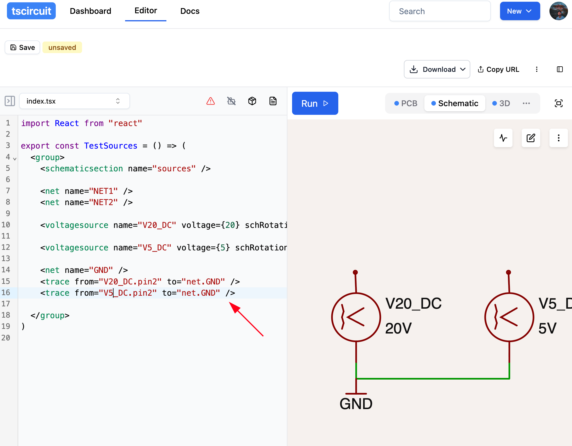
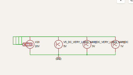
Am I not getting something or is it a known limitation? https://tscircuit.com/editor?template=blank circuit board data:application/gzip;base64,H4sIAGodU2oAA7WSXUsrMRCG/0rIlYKN27V76hFXOBxBvBGt4o2RJW7HurI7WZJUKqX/3cl+tLWtWoTuzSYz77x5Mpkpz3AIE+HshJ/wrCi1cWwAKnXs2eiCSW78RnKJEmFSpVON1
Am I not getting something or is it a known limitation?
https://tscircuit.com/editor?template=blank-circuit-board#data:application/gzip;base64,H4sIAGodU2oAA7WSXUsrMRCG/0rIlYKN27V76hFXOBxBvBGt4o2RJW7HurI7WZJUKqX/3cl+tLWtWoTuzSYz77x5Mpkpz3AIE+HshJ/wrCi1cWwAKnXs2eiCSW78RnKJEmFSpVON1rE7sO5Wj00KlsVsb5/FZ2xPImOnI6PH5Zlf0samL1Aol6UWUpdpZKgKiCW3dank7JCkjRjBtfnz/8nlVZNdzV1cnX+ue9O5UyOoPVvVfdJ6NOl4GgYzRkAD7YhIYzzt/KXI/IjNNtG6T/SVzYI1V0+QM1os3YUah3UXKCgaPibKDLuUVZi+aHObDf2pTpcrl/9sGG10bFB/smxMnVGLa1abZIRD0viXXyUMKe40RYlALB7gG6No2WmZ7Eur08N2dPYl8gNeKByrvAPDzFnxajXSiE69kManHaukzOm8AtDRLJ2whxqpUvmPlJBTh7TxWcmvB2FAnTlY5FMqhSo7L/LhiY90+uLPXOqj7z4aibCNzZaMDOQE9AaJ0/VZ1WWS1r8WtgXfAlLntgXsif4mwN5OAbv97QFD0dsE2N1tB4PtAQNxvA7YE0e7A7wJg6N/WwMG63Rdcfx7Ov97lDjjsw8j6oY+/AUAAA==
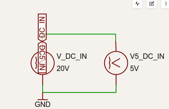
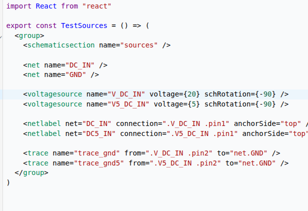
Why wouldn't flag labels be consistent? Can't move them manually either. Is it some strange use case? I just want two voltage sources injected. Seems pretty basic to me?
Just o understand, you want the netlabels there is that right?
Seve
If you simply omit them, does that get you something desirable?
Seve
One of your nets is effectively given two names i think- i may be wrong. Also generally we just omit manual netlabel elements, unless you want it for some reason (placement?)
is it because there's some hardcoded distance between elements?
Seve
No its outside the bounds of the svg
Seve
This is an “svg not being expanded to full text extent issue” cc <@1507703667237716221>
A
astrimid
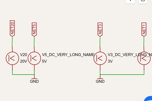
for now I just want a comon GND symbol below two voltage sources and connecting them to corresponding buses.
https://tscircuit.com/editor?template=blank-circuit-board#data:application/gzip;base64,H4sIAHQiU2oAA7WTUU/CMBSF/0rTJ0mgdIMJEkZixBhfiCLhxZplGVec2VqyFoIh/HfbjSG6SWbMnrbec+7tt7PcHQ75ArZEyS0e4DBeiUShKfiBQq+JiBHDiTkwzDjjsE3lQHCp0AykehLrJACJXHTRQO4IXTCO0HCZiPVqZF71QQZvEPsqDCQEKhQccT8Gl2GZtTKM2tp6MHNQuT65nVkHsUSyv/dtRKT8JWQzc9vcpt74RhsPqruz6R5pnqlQGkhwd9e60pX8irOznB+jnN8mFXHvJuMT2mE7j6fBOG7i2OdrP2rBIlSSvEvB9W/YGaOOKI/OW0V+ADFwpfMaoOfsjtSVgmMJkU5XJEZl+GFqU51d80sPdCuk6rHJlLem0uqRy6PVVD9M1SF2XtufDEog0kAb8JTI7ko/xsvnZ8a84SygUx2wS3plgN1aAa1edUCbdMsArXoTpNUBKekXAbukUx/go00715UBaZHOIv366NJ19u4nlQFt4hQRaZ0Bzv9ISMuWpGX9Z0vM44XxPd5/As7zcWgmBgAA
Here's a full example I'm working on:
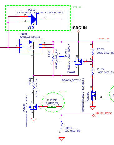
For now, I'm just trying to reproduce the schematic.
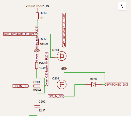
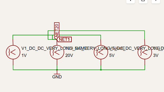
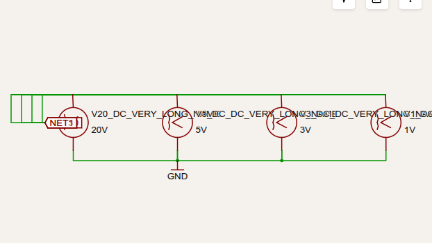
If I produce the full network on a single page, it's even more illegible. So I'm trying to split into groups. But I keep fighting with label placement and long names overlapping with schematic or with other labels. Manual label placement doesn't work, as I can't drag them.
^^ CC <@1079361271687807026>
You definitely need to make sure name is defined for every trace, some of those names are really long as well 🤔
Seve
<@1079361271687807026> check out his reference schematic on the right- we should be able to create clean reference schematics like that
Seve
we might need a property like hideNetLabel to avoid cluttering
A
astrimid
it seems the node placement only allows for 3 symbol names
Seve
<@1525187702029549659> fwiw you will need to use schX/schY to set the positions of symbols for a schematic with that level of complexity- you may already have discovered this
Seve
> node placement only allows for 3 symbol names
Hmm i don't follow
A
astrimid
yeah, I'm trying, but those flags won't budge
Seve
yea the net labels are basically always automatic right now-
Mustafa has been able to create a lot of schematics that match references but i'm not sure what his magic is
Seve
yea i think until we adjust the algorithm to pack those properly your only hope is to use schX/schY on each <voltagesource
A
astrimid
Is this the way to do?
```
import manualEdits from "./manual-edits.json";
export const PowerPathControl = () => (
<board routingDisabled manualEdits={manualEdits}>
```
The positions seem to reset after I press run
Seve
We are mostly deprecating manualEdits, but it may work- schX/schY props work for all symbols and are our current recommendation
A
astrimid
hm. why does schX and schY coordinate system start with negative numbers? I would expect 0,0 to be top left
M
Mustafa7
Is this auto-placed?
A
astrimid
yes
M
Mustafa7
Ok will try to fix it thanks
M
Mustafa7
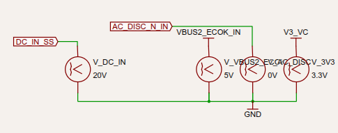
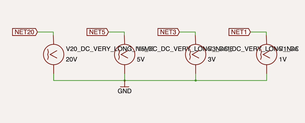
<@1525187702029549659> I couldnt reproduce the issue, this is the result with autolayout.
I am trying to fix the autolayout to consider the names
M
Mustafa7
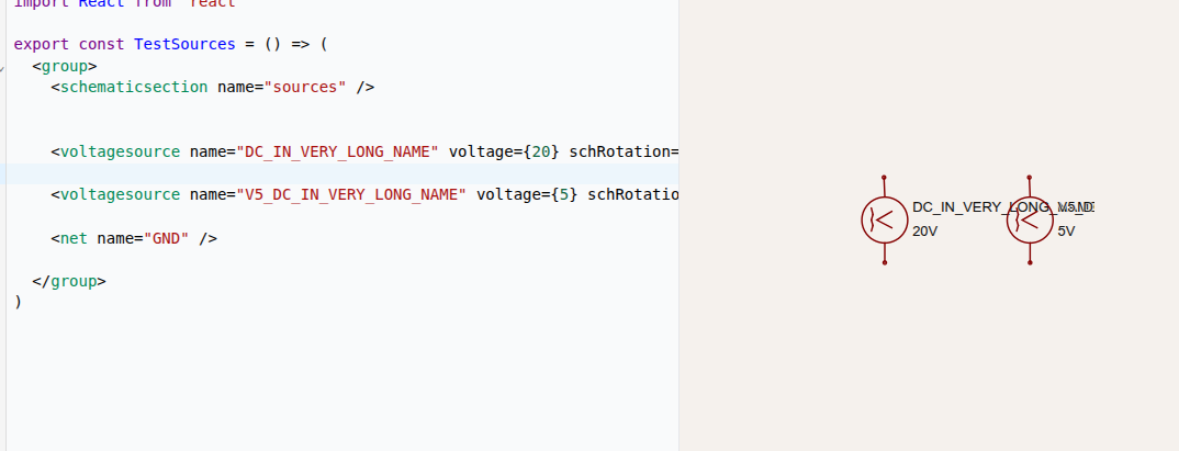
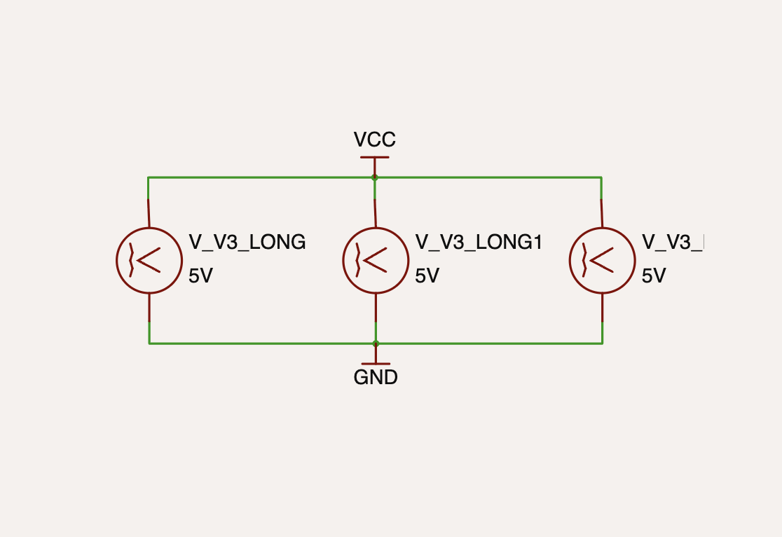
Is the real use cases use this lengthy names: "V5_DC_VERY_LONG_NAME"?
M
Mustafa7
I dont think so right?
A
astrimid
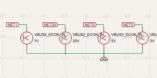
For this specific case not really, but consider I'd like to put out the resistor specification on a schematic, say "300k_0402_5%" or the name the signal as `${BUSNAME}_${SIGNAL}_${DIRECTION}` to specify what controller it's coming from, what the pin name is and whther it's a sensing or a control signal, eg. VBUS2_ECOK_IN
A
astrimid
It would be ok if the component label displayed vertically, like the net labels, but I can't find the option to rotate the label
M
Mustafa7
VBUS2_ECOK_IN will work and won't overlap
M
Mustafa7
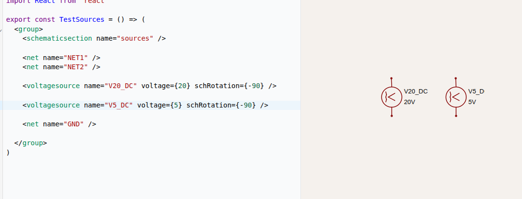
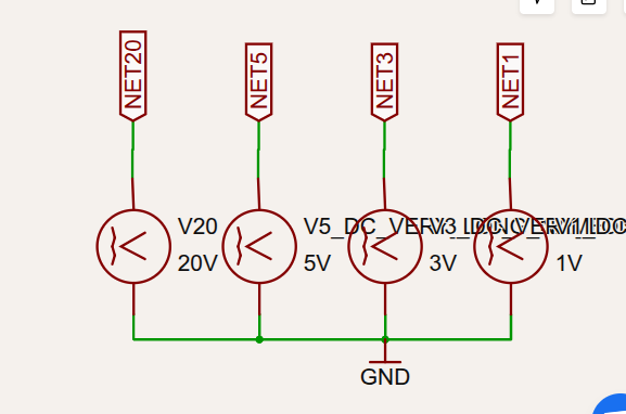
It's just that very long names are not handled well currently like "V20_DC_VERY_LONG_NAME" these type of long names
A
astrimid
so, is there a limit of number of characters that are handled? BTW, I've just discovered the show grid option. Still strange numbering I would say, but at least I can see the coordinates:
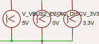
VBUS2_EC_OK_IN still overlaps with autorouting
```
import React from "react"
export const TestSources = () => (
<group>
<schematicsection name="sources" />
<net name="NET20" />
<net name="NET5" />
<net name="NET3" />
<net name="NET1" />
<trace from="VBUS2_ECOK_IN.pin1" to="net.NET20" />
<trace from="VBUS3_ECOK_IN.pin1" to="net.NET5" />
<trace from="VBUS4_ECOK_IN.pin1" to="net.NET3" />
<trace from="VBUS5_ECOK_IN.pin1" to="net.NET1" />
<voltagesource name="VBUS2_ECOK_IN" voltage={20} schRotation={-90} schSectionName="sources" />
<voltagesource name="VBUS3_ECOK_IN" voltage={5} schRotation={-90} schSectionName="sources" />
<voltagesource name="VBUS4_ECOK_IN" voltage={3} schRotation={-90} schSectionName="sources"/>
<voltagesource name="VBUS5_ECOK_IN" voltage={1} schRotation={-90} schSectionName="sources"/>
<net name="GND" />
<trace from="VBUS2_ECOK_IN.pin2" to="net.GND" />
<trace from="VBUS3_ECOK_IN.pin2" to="net.GND" />
<trace from="VBUS4_ECOK_IN.pin2" to="net.GND" />
<trace from="VBUS5_ECOK_IN.pin2" to="net.GND" />
</group>
)
```
So the 0,0 coordinate is dynamic as the schematic grows, so I should really specify all the coordinates with manual route, as automatic placement will mess up with coordinates
A
astrimid
E.g. if I just want to move just one volatage source lower, the coordinates I target will change as the schematic will try to find a new center and my schX/Y will be targeting a moving goalpost
M
Mustafa7
If you want to use mix of auto and manual placement then use schx/schY for component you want to place manually and use schAutoLayoutEnabled prop on board element.
Seve
<@1079361271687807026> schAutoLayoutEnabled should be on by default!
M
Mustafa7
So whenever someone uses schX/schY the auto layout turned off for all the components, we would want it to be on by default right so that user won't have to pass schAutoLayoutEnabled={true} when using mixed layout?
<@757706909351411845>
Seve
yea, it should just be on
M
Mustafa7
Sg!
Seve
the auto layout used to be super broken, that's why it's off by default
Seve
but we need to start fixing auto layout etc so best to turn it on
A
astrimid
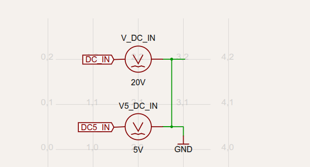
To summarise the thread, auto layout doesn't work very well wrt label placement, so you need to use schX/schY. <netlabel> also support X/Y positionining. schMaxTraceDistance controls how far the nodes should be located so that nets are split into separate netlabels. schX/schY coordinate system uses cartesian: `-infinity` at the top, `+infinity` at the bottom, `-infinity` to the left, `+infinity` to the right
```
import React from "react"
export const TestSources = () => (
<board routingDisabled schMaxTraceDistance={1}>
<net name="DC_IN" />
<net name="GND" />
<net name="DC5_IN" />
<voltagesource
name="V_DC_IN"
voltage={20}
schRotation={0}
schX={2}
schY={2}
/>
<voltagesource
name="V5_DC_IN"
voltage={5}
schRotation={0}
schX={2}
schY={0.5}
/>
<netlabel net="DC_IN" connection=".V_DC_IN .pin1" anchorSide="bottom" />
<netlabel net="DC5_IN" connection=".V5_DC_IN .pin1" anchorSide="bottom" />
<netlabel
net="GND"
connection=".V5_DC_IN .pin2"
anchorSide="top"
schX={3}
schY={0.3}
/>
<trace name="trace_v" from=".V_DC_IN .pin1" to="net.DC_IN" />
<trace name="trace_v5" from=".V5_DC_IN .pin1" to="net.DC5_IN" />
<trace name="trace_gnd" from=".V_DC_IN .pin2" to="net.GND" />
<trace name="trace_gnd5" from=".V5_DC_IN .pin2" to="net.GND" />
</board>
)
```