← Back to community index
# contributor·Active

Abse - I added some new stuff of the https://ca...

I added some new stuff to the https://cad component viz.vercel.app/ check it out

Started by AbseJun 1, 202648 messages

Discussion

Last active 23 days ago · plain text
Abseoriginal post
I added some new stuff to the https://cad-component-viz.vercel.app/ check it out
Seve
it looks really good!
Seve
definitely should be useful!
Abse
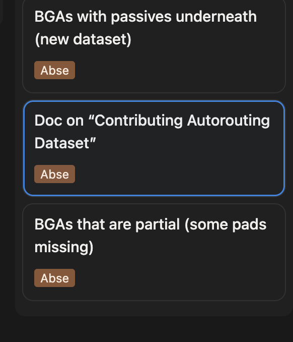
<@757706909351411845> wdyt about this https://docs-git-fork-abse2001-main-tscircuit.vercel.app/contributing/contributing-autorouting-dataset
Abse
let me know if it's messing something or something is not correct
Seve
This is a good start but it needs a lot more references, link to the bootstrapping repos and dataset guidelines rather than including all the information in the doc
Seve
Also add more details about adding a fixture with the dataset to the autorouting repo
Seve
Otherwise looking good, getting there
Abse
also do you want the BGA datasets on there own repos ?
Abse
<@757706909351411845>
Abse
also can you check the component detection and topology generatioan for nested qfp components https://capacity-node-autorouter-git-fork-abse2001-qfp-tscircuit.vercel.app/?fixtureId=%7B%22path%22%3A%22fixtures%2Fbenchmarks%2Fdataset-srj18.fixture.tsx%22%7D
Abse
<@757706909351411845>
Abse
https://capacity-node-autorouter-git-fork-abse2001-qfp-tscircuit.vercel.app/?fixtureId=%7B"path"%3A"fixtures%2Fbenchmarks%2Fdataset-srj18.fixture.tsx"%7D
Abse
if you check sample 8
Abse
we have a passive components under qfp issue not sure how to handel them
Seve
hello sorry for the delay
Seve
<@398467566588264449> the QFP topology generation looks really good?
Seve
do we know if this has any impact on performance (hopefully good) or on benchmark?
Abse
yes
Abse
we Improved one board
Abse
and failing in one
Abse
so no change but I'm working on a fix for the failling one
Abse
https://github.com/tscircuit/tscircuit-autorouter/pull/1332
Abse
the failling sample is 8 in the srj18
Abse
it fail for the passive components on top of the QFP
Abse
<@757706909351411845> how is this https://docs-isjj0nxcm-tscircuit.vercel.app/contributing/contributing-autorouting-dataset
Abse
https://github.com/tscircuit/dataset-srj19/pull/1
Abse
<@757706909351411845> can we merge this ? https://github.com/tscircuit/docs/pull/700
Abse
I can't merge
Abse
also this is needed for footprinter https://github.com/tscircuit/kicad-to-circuit-json/pull/139
Abse
<@757706909351411845>
Abse
<@757706909351411845> can I get a review?
Abse
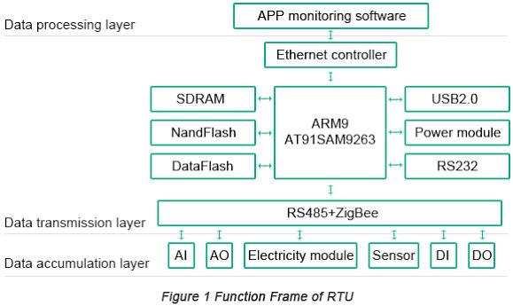
https://github.com/tscircuit/system-diagram-proposal/pull/1
Seve
Some images failing for me but the first 6 are good
Seve
You probably need some simple ones and some different styles 🤔 a lot of system diagrams are pretty simple flowchart-ish things. Eg But i think this is pretty good
Seve
Now u gotta generate them
Abse
hey <@757706909351411845>
Abse
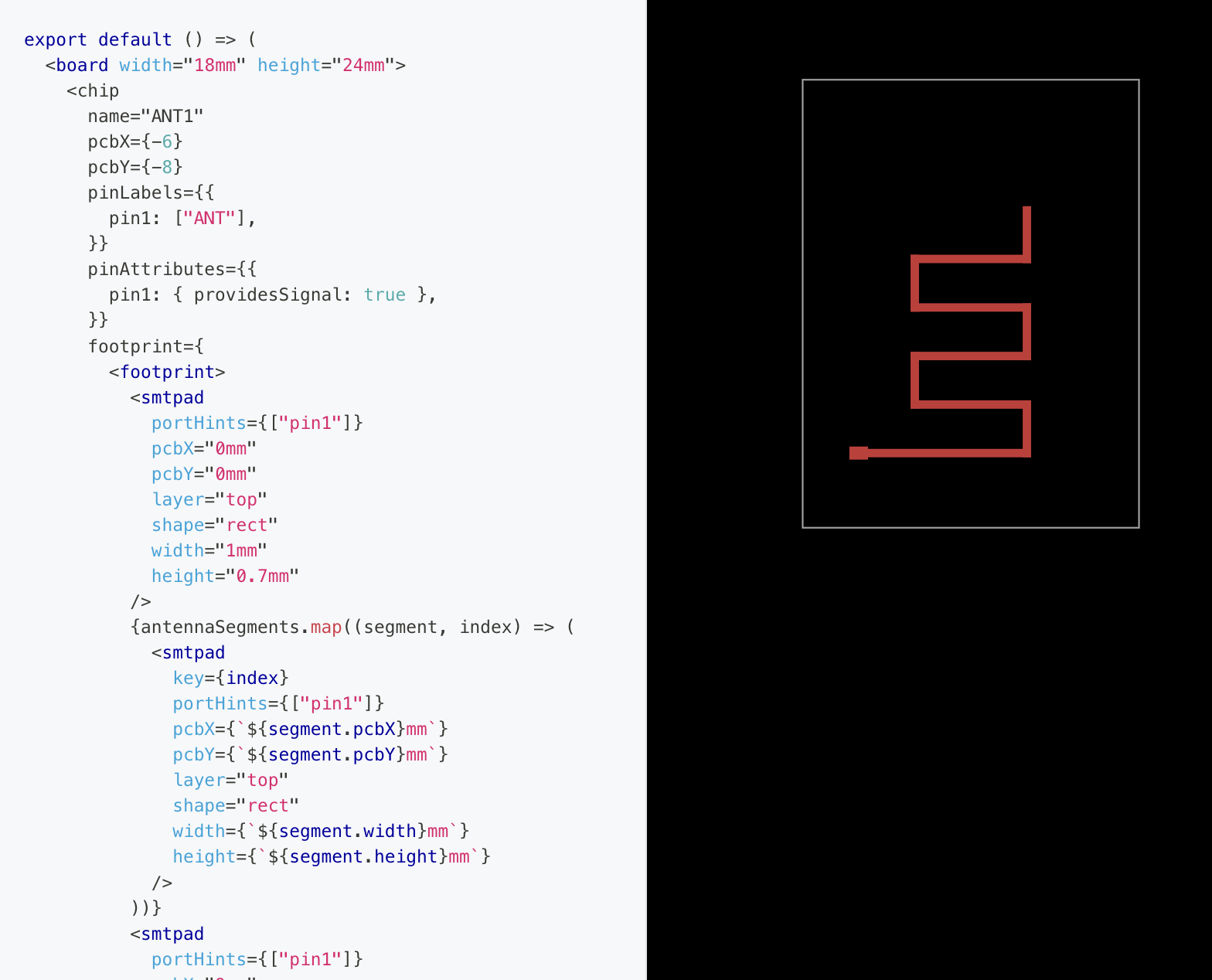
``` const antennaPoints = [ { x: 0, y: 0 }, { x: 9, y: 0 }, { x: 9, y: 2.6 }, { x: 3, y: 2.6 }, { x: 3, y: 5.2 }, { x: 9, y: 5.2 }, { x: 9, y: 7.8 }, { x: 3, y: 7.8 }, { x: 3, y: 10.4 }, { x: 9, y: 10.4 }, { x: 9, y: 13 }, ] const traceWidth = 0.45 const antennaSegments = antennaPoints.slice(0, -1).map((start, index) => { const end = antennaPoints[index + 1] const horizontal = start.y === end.y return { pcbX: (start.x + end.x) / 2, pcbY: (start.y + end.y) / 2, width: horizontal ? Math.abs(end.x - start.x) + traceWidth : traceWidth, height: horizontal ? traceWidth : Math.abs(end.y - start.y) + traceWidth, } }) export default () => ( <board width="18mm" height="24mm"> <chip name="ANT1" pcbX={-6} pcbY={-8} pinLabels={{ pin1: ["ANT"], }} pinAttributes={{ pin1: { providesSignal: true }, }} footprint={ <footprint> <smtpad portHints={["pin1"]} pcbX="0mm" pcbY="0mm" layer="top" shape="rect" width="1mm" height="0.7mm" /> {antennaSegments.map((segment, index) => ( <smtpad key={index} portHints={["pin1"]} pcbX={`${segment.pcbX}mm`} pcbY={`${segment.pcbY}mm`} layer="top" shape="rect" width={`${segment.width}mm`} height={`${segment.height}mm`} /> ))} <smtpad portHints={["pin1"]} pcbX="9mm" pcbY="13mm" layer="top" shape="rect" width="0.01mm" height="0.01mm" /> </footprint> } /> </board> ) ```
Abse
Shared an attachment
Abse
I managed to make the antenna like this, but this is a hack no ?
Abse
not sure if we have manual trace component or prop that I'm not aware of ?
Abse
the trace need from to and from the image he sent the antenna don't have to
Abse
https://github.com/tscircuit/system-diagram-proposal/pull/3
Abse
<@757706909351411845>
Seve
Did we get in ant of the antenna stuff? Your code there is a crazy hack just use pcbPath of trace
Seve
The antennaPoints var is nice but the antenna doesnt look right to me- make sure its accurate
Abse
https://github.com/tscircuit/system-diagram-proposal/pull/4
Abse
<@757706909351411845> can you review this

Want to add to the conversation?

Reply in Discord so your notes stay connected to the source.
Continue in Discord ↗