← Back to community index
# designreview·Active

@Seve https://tscircuit.com/

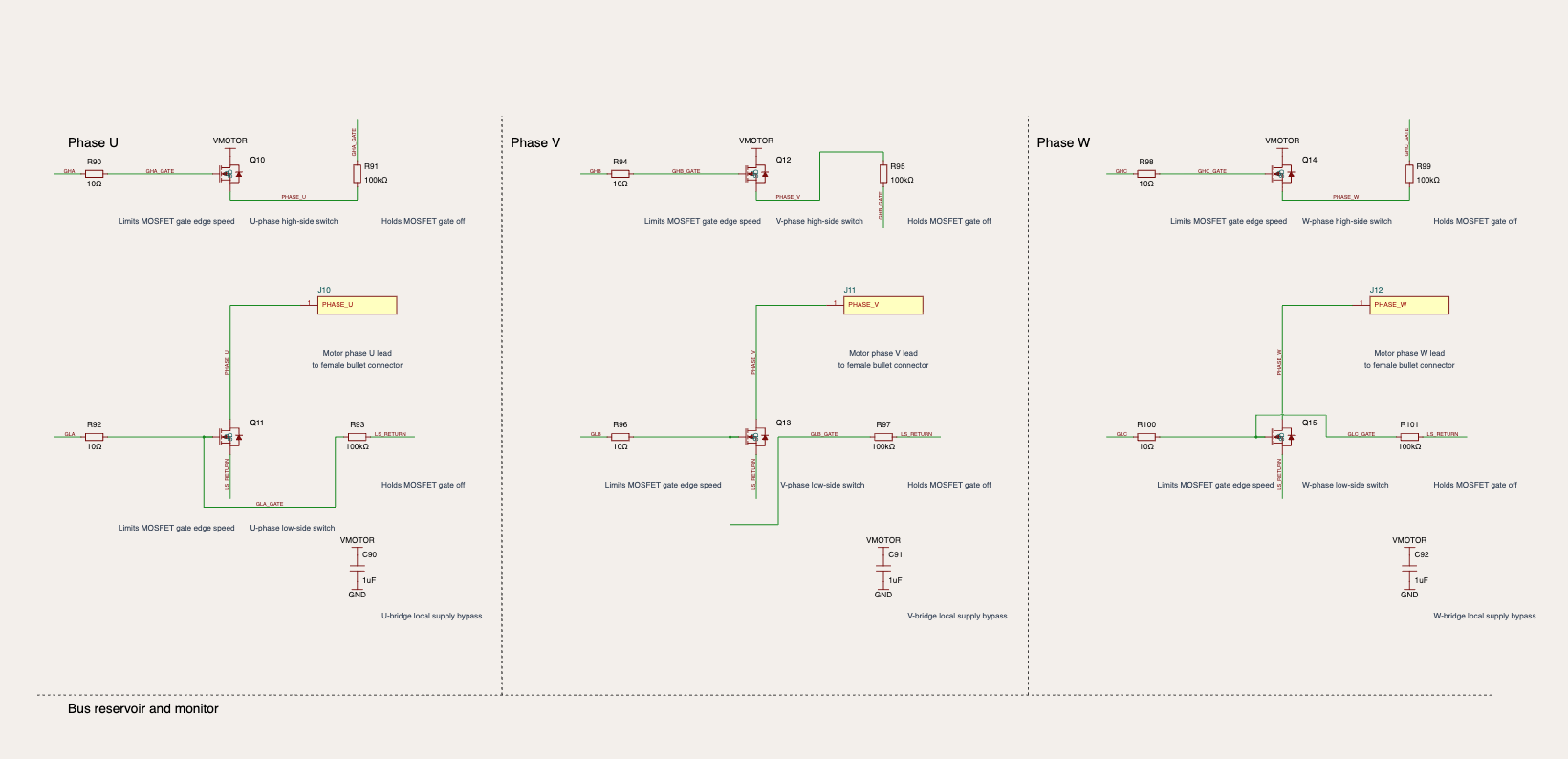
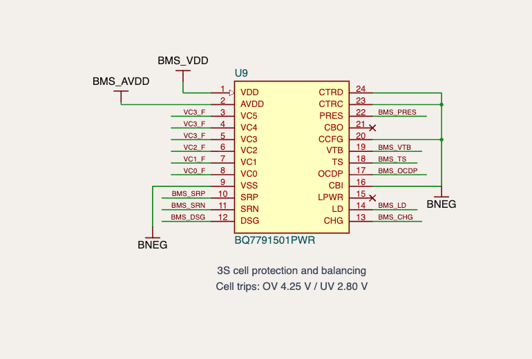
non standard USB C footprint, also issues with it each motor connection is a separate component (a single plated hole = single component?) all said that page is maybe the cleanest but you can use schematicbox for that rather than 3 separate components 3S cell protection i thought

Started by SeveOct 2, 2026100 messages

Discussion

Last active 3 days ago · plain text
Seve
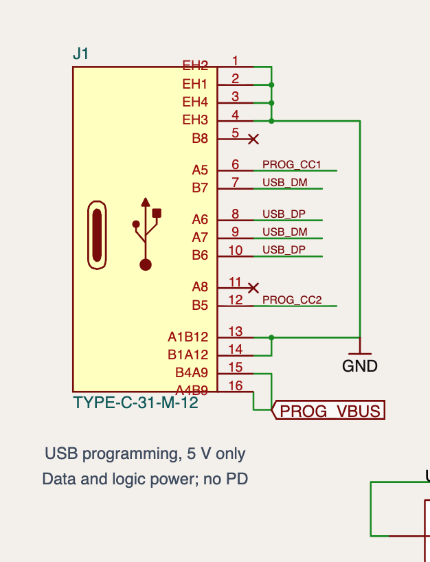
non-standard USB-C footprint, also issues with it
Seve
all said that page is maybe the cleanest
Seve
but you can use schematicbox for that rather than 3 separate components
Seve
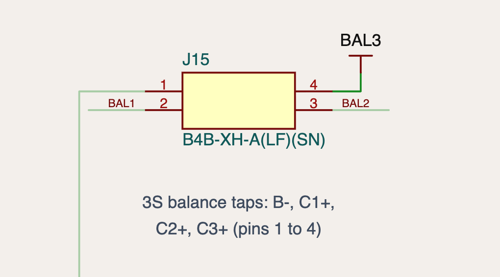
3S cell protection- i thought you were using single cell? Am I confused? What battery does this go with? (I shouldn't need to ask!!!)
Mustafa7
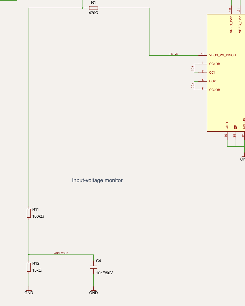
https://tscircuit.com/MustafaMulla29/rp2040-bldc-motor-controller-new#files <@757706909351411845> review please! The schematic-analysis reports a lot of false positives or wrong suggestions, am working on fixing them. The battery is "one 3S, 2200 mAh LiPo battery pack" ```ONE 3S LiPo battery ├── Thick red/black wires → XT60 plug → J13 └── Four thin wires → small JST-XH plug → J15``` I have improved the schematic to follow the references.
Seve
i have to keep telling people this, but generally you _never mix vertical and side connectors on the same board_, you have both vertical and side connectors, just go with the side connectors (those are usually more stable and available), triple check that everything plugs in!!!
Seve
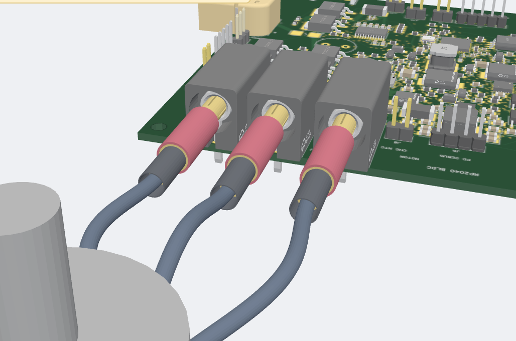
i'm looking at your banana plug connector and i'm not sure it's right, triple check these things, if they don't match it'll be a waste of money!
Seve
i think your motor connector is wrong as well
Seve
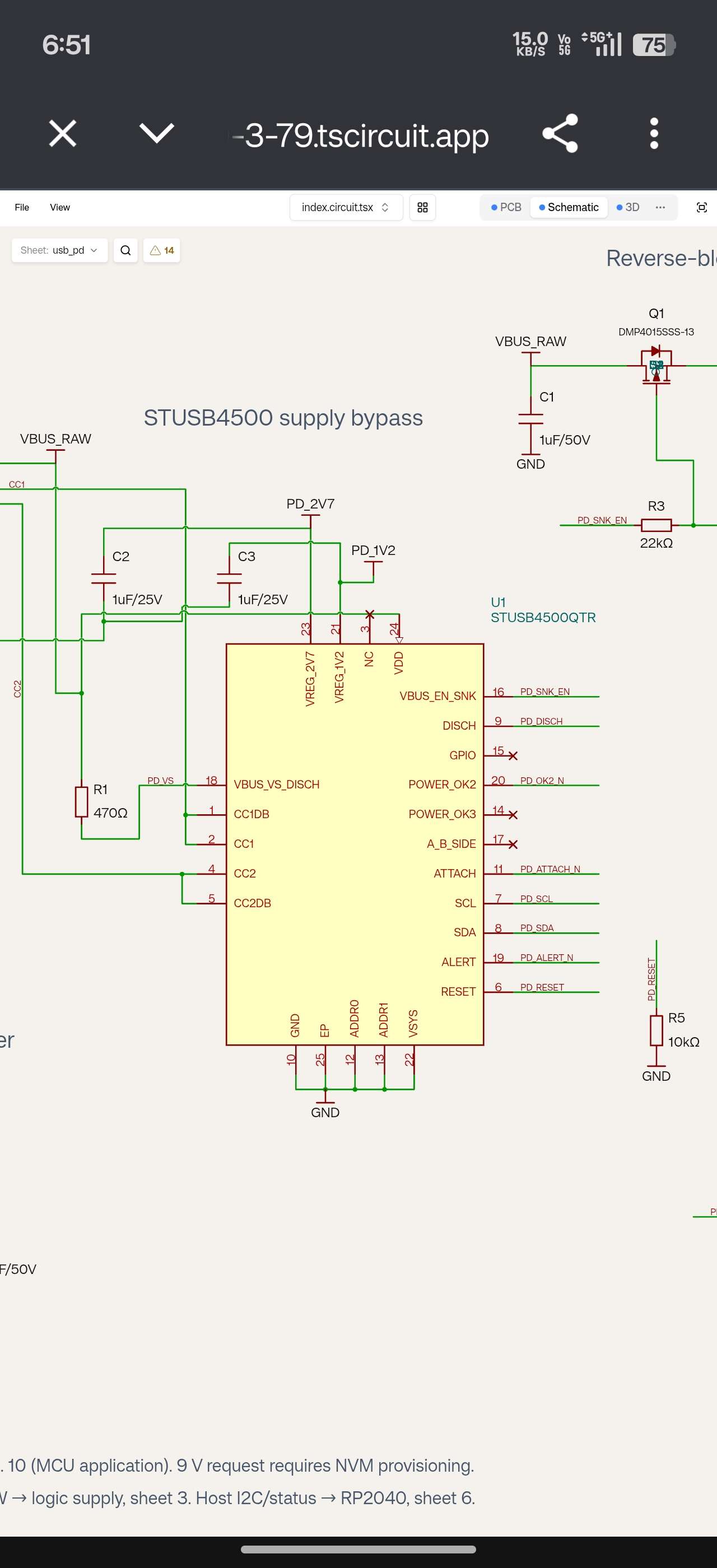
yea the schematic still needs a lot of work to be readable but it's a good one to chase to get all the issues. One of the big issues is just really long "schematic subcircuits" like this one. Ideally the "path to ground" or "path to power" is all visible from the pin
Seve
no absolutely not
Seve
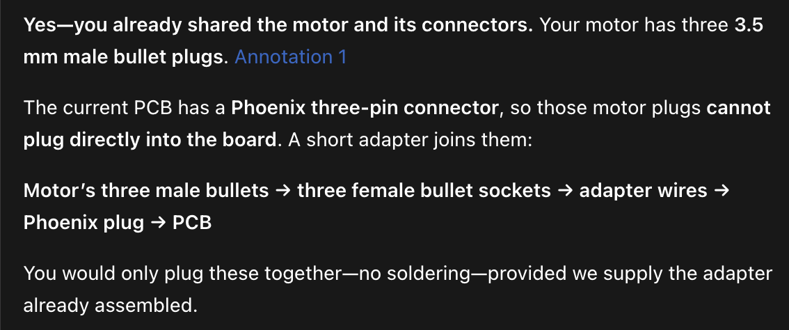
the entire thing i'm avoiding is adapter wires
Seve
getting annoyed about this, you should now do a full assembly
Seve
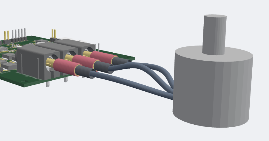
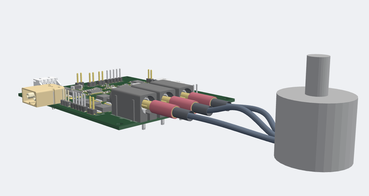
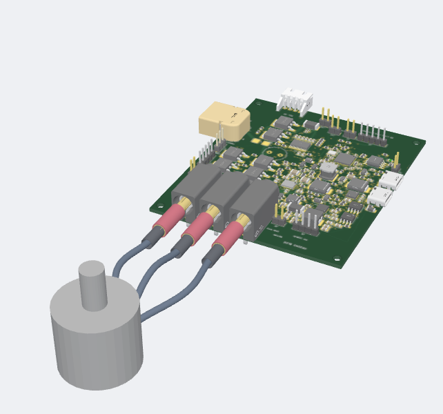
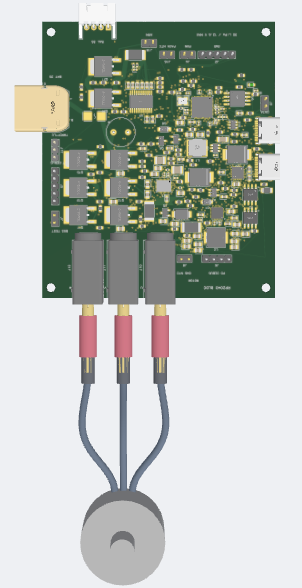
i.e. you need to create the entire system in 3d in tscircuit assembly components with <assembly.cable /> etc. because it seems like you cannot visualize the system
Seve
you may need to add support for the particular cables you're using. For the model, you will want to probably create this via e.g. Opus and build123d
Seve
https://cleanshot.com/share/3tDGd23y
Mustafa7
<@757706909351411845>
Mustafa7
cannot see assembly on 3d viewer, this is from local server. Do we have to create a new package integrating the assembly?
Seve
is tscircuit up to date
Seve
btw let me know when you're asking for review, i know you sent a link there but based on the pin headers and empty space on the board i'm guessing you're not ready for review yet
Mustafa7
yes
Mustafa7
it was 70x65 before but after adding sockets it became 80x95 thats why there is some empty space left
Mustafa7
those sockets are big
Mustafa7
Ill see until where i can decrease the size
Seve
i would investigate that bug
Seve
don't worry about decreasing the size yet
Seve
you need to get rid of all these pin headers and get your board ready
Seve
why do you have a million pin headers
Seve
oof
Seve
yea you need to include all that in your assembly and source it all
Seve
if you don't need it don't put it on
Mustafa7
Removed pin headers and shinked it down by 5mm https://tscircuit.com/MustafaMulla29/rp2040-bldc-motor-controller-new#files
Mustafa7
Let me know if any issues, headed to bed. I'll fix in morning
Seve
your banana plugs are facing the wrong way i think
Seve
you need a power switch
Seve
yea try to complete a full assembly
Mustafa7
Wdym? You only said to do motor assembly right?
Seve
just make sure everything needed to run the motor is connected, if there's something needed to run the motor, make sure it's added
Mustafa7
<@757706909351411845> The board includes USB-PD charging and battery protection, each with a separate battery-temperature input. Should we keep two external temperature probes, or would you prefer a simpler temperature-sensing arrangement?
Seve
i'm not sure
Seve
what's the reference design do?
Mustafa7
reference design doesnt have battery
Seve
why do we need a battery?
Seve
i really just want to control a motor with USB PD and USB DATA
Mustafa7
You recommended me to add battery right
Seve
i think there is a lot of stuff added
Mustafa7
usb pd charges the battery
Seve
i'm not designing the product
Seve
i said that a battery can help with current draw
Seve
you're the product designer but i think we probably don't want the battery
Seve
if usb-pd can power it
Seve
especially because the board is huge right now
Mustafa7
ok ill remove battery
Seve
ask ai, understand the product, redesign as needed, you have to make this product SELL which means it's gotta be good
Seve
i don't think people are going to want to buy a battery and we wouldn't package a battery i think
Seve
don't just do random stuff that i'm saying, i'm here to help not design the product
Seve
you should be able to answer WHY for every design decision
Mustafa7
https://tscircuit.com/MustafaMulla29/rp2040-bldc-motor-controller-new#files Please review when you get time, am probably asking for too many reviews! Build is running still not completed yet. THis includes the motor adapter etc assembly.
Rishabh
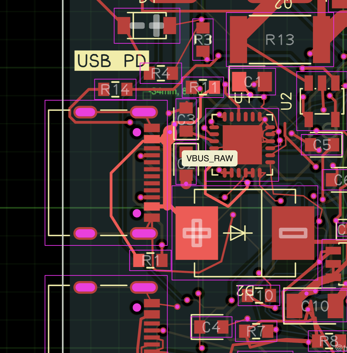
The power traces should be on the outer layers
Rishabh
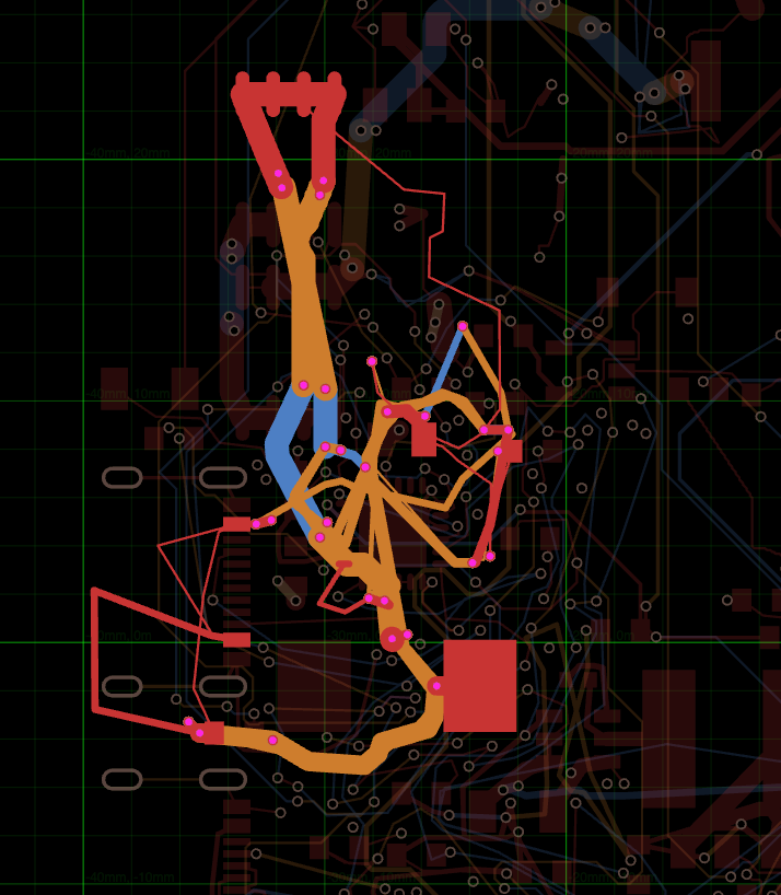
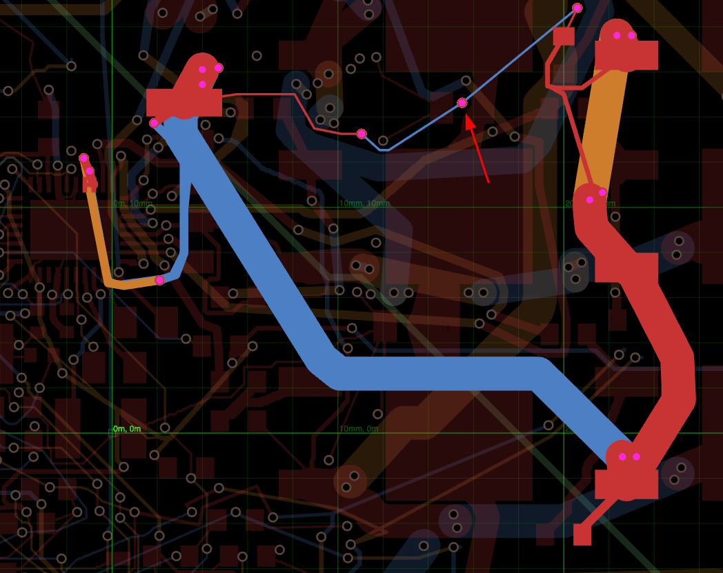
I see via stitching happening on your board, some of them look uncessary
Rishabh
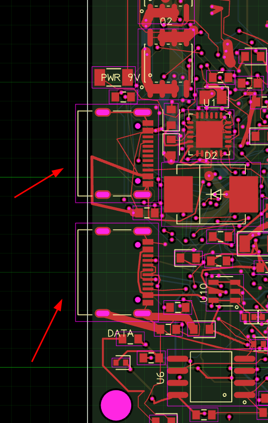
Add knockout silkscreen to these, confusing which one is data and which is pwr
Rishabh
I think get a review from AI first, I made ai review this and it gives a lot of placement issue and the width of traces
Mustafa7
<@757706909351411845> <@809856037376491570> https://tscircuit.com/MustafaMulla29/rp2040-bldc-motor-controller-new#pcb review please
Rishabh
Your schematic is messed up, can't read the labels on any of the components. Everything is overlapping
Mustafa7
The one you shared is showing the ports right?
Mustafa7
I think that is a circuit to svg ports drawing issue
Mustafa7
https://tscircuit.com/MustafaMulla29/rp2040-bldc-motor-controller-new#pcb <@757706909351411845> can you take a look
Seve
this is looking really good, can you make sure the PD is configurable
Mustafa7
<@757706909351411845> this is configured for 9v
Seve
yes, that's why I commented to say that you need to make it configurable
Seve
(is there any reason not to?)
Mustafa7
STUSB4500 the one am using supports upto 20v, so 20v should be the last range right? i think configurable till 20v is good right?
Mustafa7
you want it to be configurable between 5, 9, 15, 20v?
Mustafa7
https://tscircuit.com/MustafaMulla29/rp2040-bldc-motor-controller-new#pcb <@757706909351411845> For 5v codex says this: ```Some of the USB’s 5 V is lost in the cable and board, so the motor-driver chip may receive less than the 4.5 V it needs. If that happens, the motor may fail to start or stop when working harder.```
Seve
the motor driver should be receiving usb pd voltage no?
Seve
msybe join discord voice so we can talk about it
Seve
a motor driver might not even work at 5v
Seve
do you have a multi-color LED on this board? I don't see it
Seve
those are super important
Mustafa7
Yes thats correct
Mustafa7
Ill add those now
Seve
> Yes thats correct fwiw this is another case of people wasting my time with "AI said this". Don't tell me what AI says, ask me a question or tell me I'm wrong etc. but idgaf what AI says. I have no idea why you posted the following quote, what was I supposed to say? If you're requesting PD voltage then this quote makes no sense, so i have no idea why you posted it or why you responded that you were getting pd voltage. > Some of the USB’s 5 V is lost in the cable and board, so the motor-driver chip may receive less than the 4.5 V it needs. > If that happens, the motor may fail to start or stop when working harder.
Seve
"AI said this" = "Fake engineering"!!!
Seve
This is to say I have no idea why you posted that quote, now i'm sitting here trying to think of why you posted that quote if you know that it's requesting pd voltage
Mustafa7
I meant that is that true? that 5v wont work reliably?
Seve
of course you can't power the bldc on the 5v line
Seve
that's the entire point of the pd line
Seve
again i have no idea what you're talking about, why would the motor ever receive 5v
Mustafa7
ok i never knew these, i dont have much knowledge thats why i asked
Seve
yes but mustafa you literally can't not know that, that is so critical
Seve
do research etc. there are mistakes but you really have to understand that stuff really deeply
Seve
you should watch a couple hours of videos on the design of BLDC controllers for example
Seve
https://www.youtube.com/shorts/71tAOaD3kfI
Mustafa7
Yes watched some videos of usb pd

Want to add to the conversation?

Reply in Discord so your notes stay connected to the source.
Continue in Discord ↗