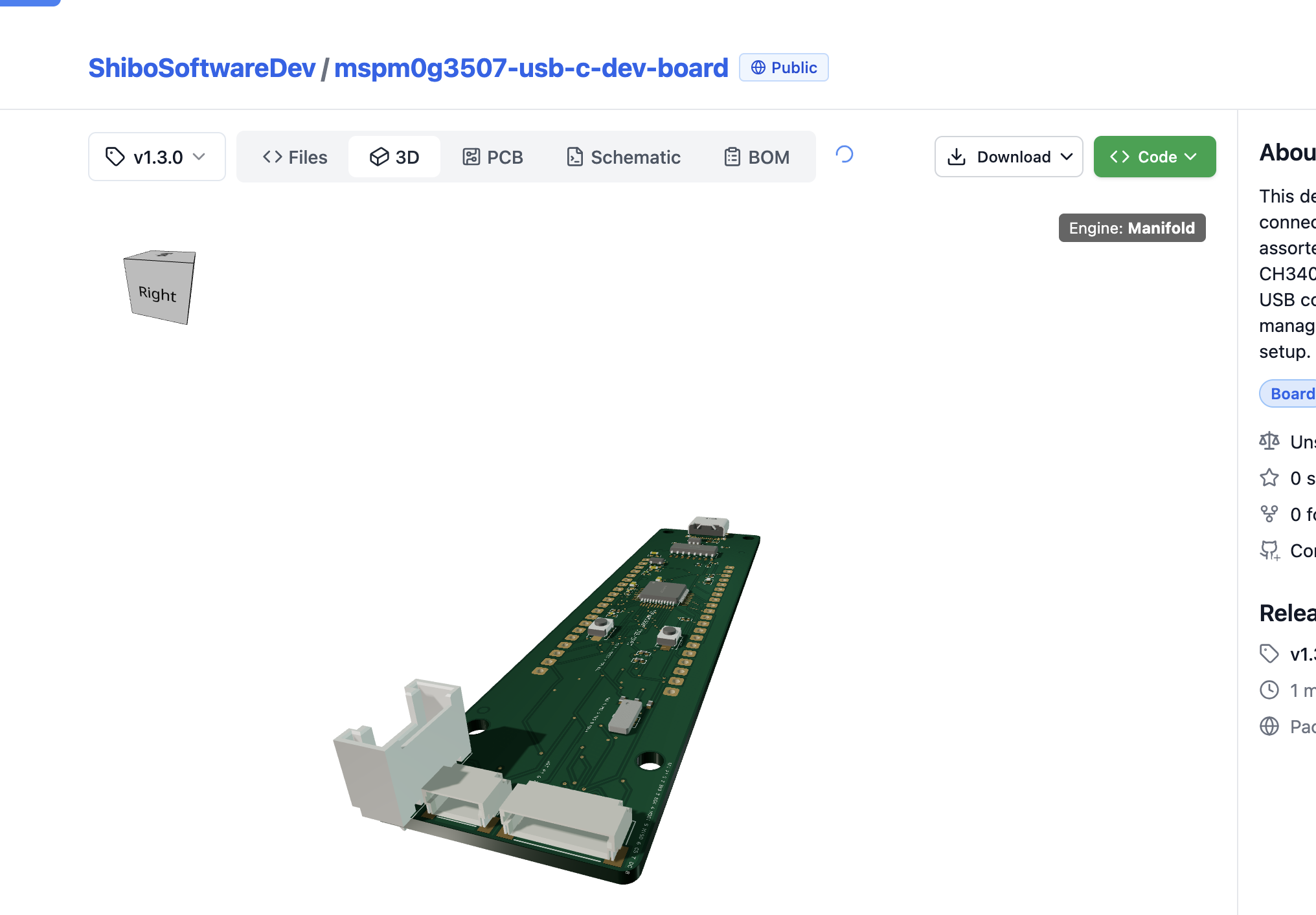
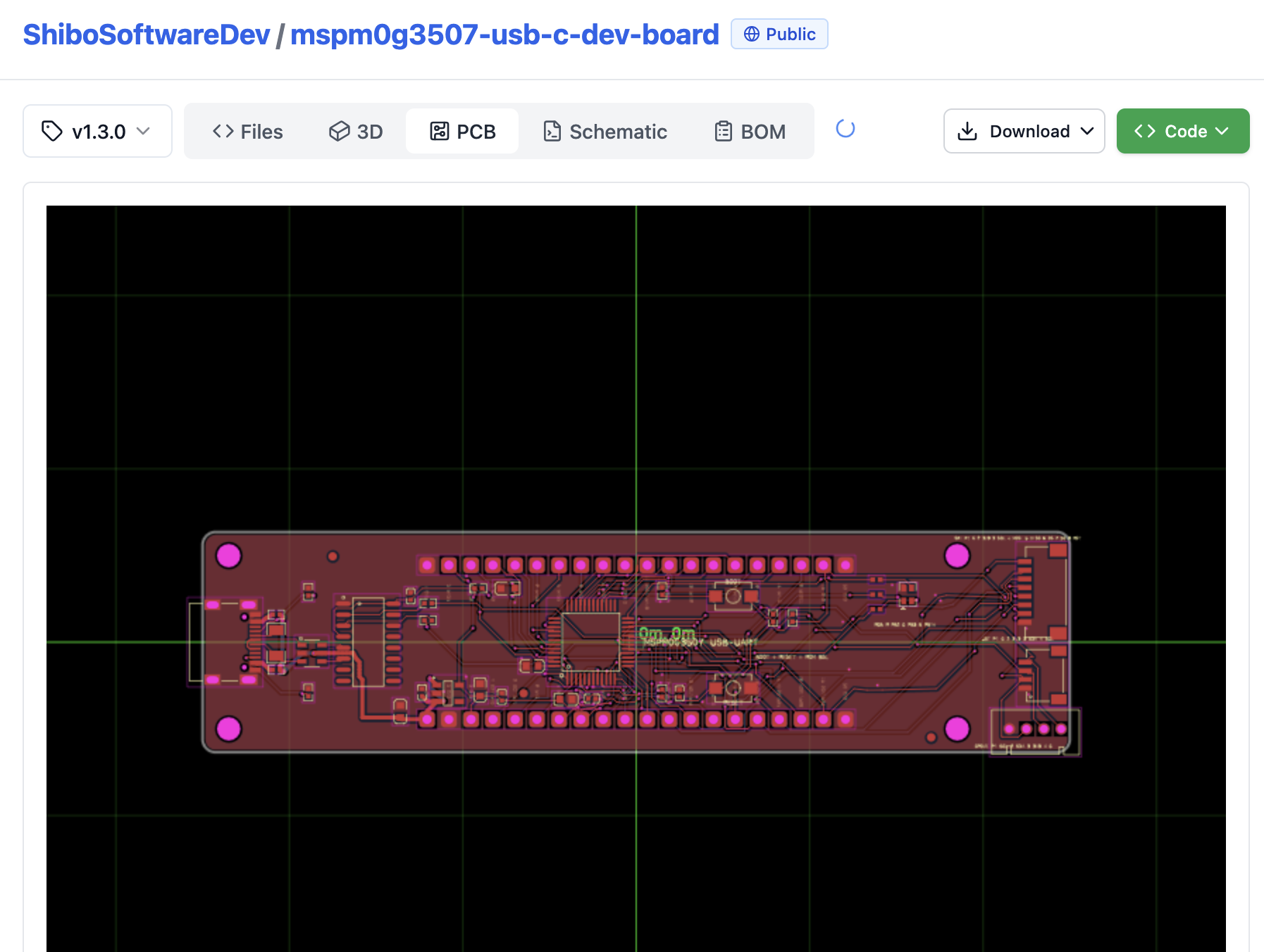
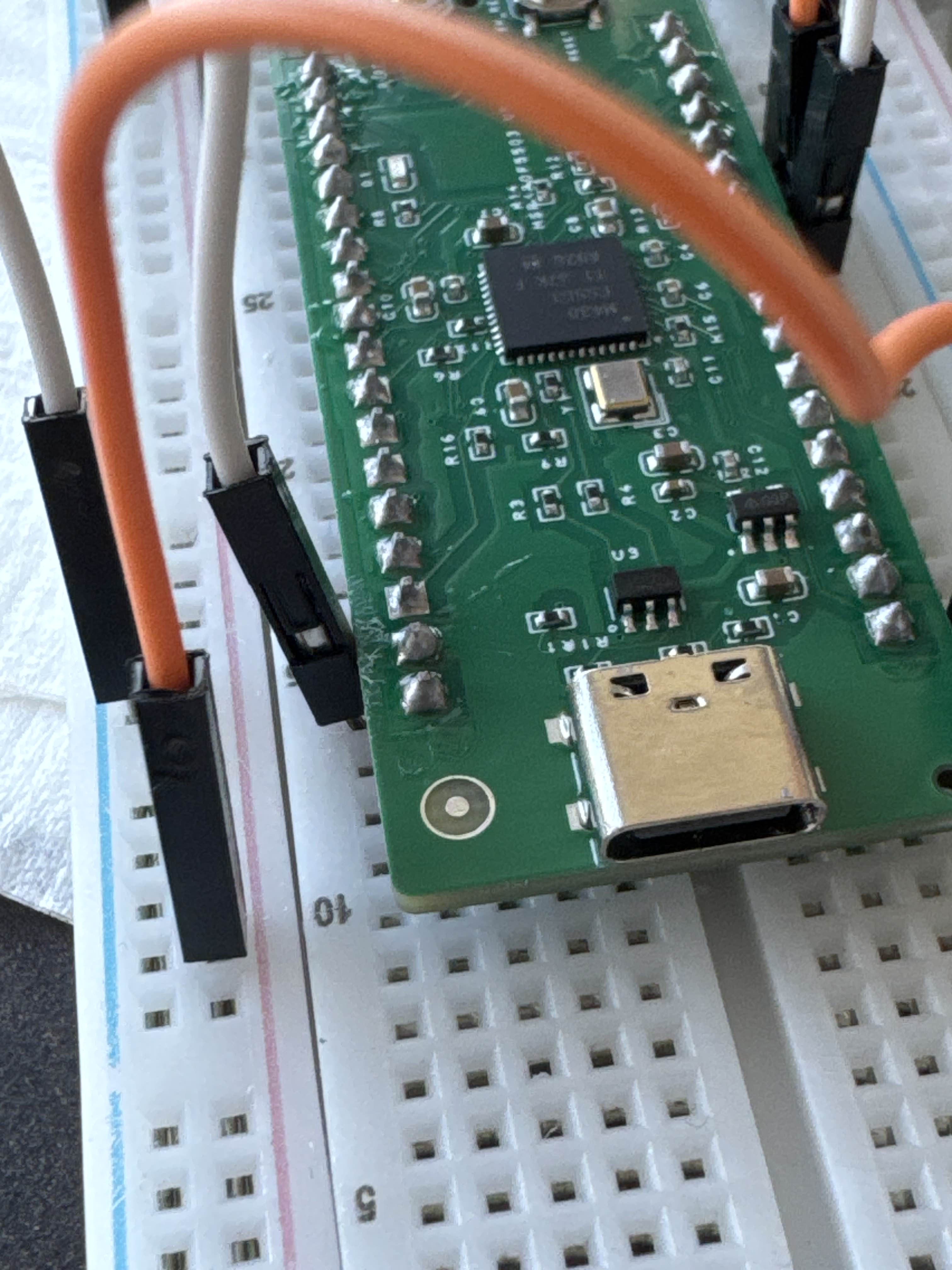
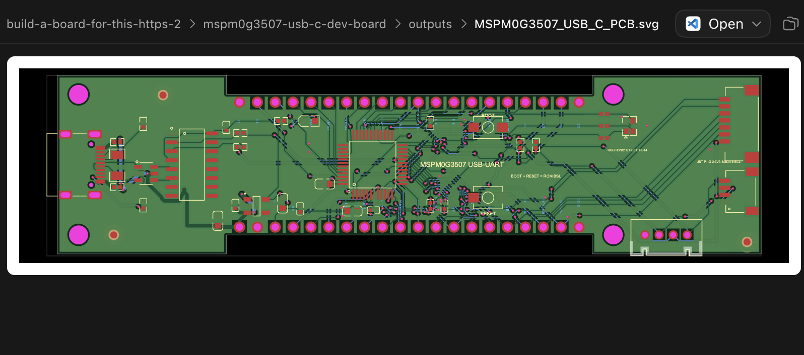
do you see how the board edge makes it difficult to insert a breadboard wire without bending it? In fact the width in general makes it a bit hard to wire tbh
Seve
your thin version is much better in this way
Seve
but i don't think it needs to be that long
shibo
oh, i see
shibo
<@757706909351411845> this is not what i intended but look what i got 😂
it's not programmable i think- is there a programming jumper....
shibo
what is the programming jumper?
Seve
we just discussed in voice but 99% of the time you can't program over USB
Seve
especially because you're using a chip to facilitate USB
Seve
you have to break out SWD (SoftWare Debug) in a JST to program 99% of chips
Seve
you can also just ask ai "how do i program this" and if it suggests connecting to pin headers you know you messed up b/c then i have to solder 😁
shibo
the agent did tell me it's programmable with usb, here's it's response to your concern:
The reviewer raised a reasonable question, but his conclusion—“it’s not programmable”—is incorrect for this MCU and board.
TI explicitly documents that the MSPM0G3507:
- Ships with its ROM bootstrap loader enabled.
- Can program flash over UART.
- Uses PA10 as default BSL TX and PA11 as default BSL RX.
- Uses PA18 as an active-high BSL-invoke input.
- Enters BSL automatically when blank.
MSPM0G3507 datasheet
Our board connects exactly those signals:
- CH340 TX → PA11/BSL RX
- PA10/BSL TX → CH340 RX
- BOOT button → PA18 high
- RESET button → NRST low
- PA18 has a normal-state pulldown
TI’s own programming documentation describes using PC software with a USB-to-UART bridge, so the reviewer’s statement that the bridge makes USB programming unlikely is backwards—the bridge is what enables it. TI BSL implementation guide
What is valid in his feedback:
- This is not native USB or Pico-style UF2.
- The CH340 cannot automatically toggle BOOT and RESET in this design; you must use the buttons manually.
- A dedicated keyed SWD connector would make debugging and recovery more convenient.
- The board exposes SWDIO, SWCLK, RESET, 3V3 and GND on the headers, but not as one convenient JST/Tag-Connect socket.
- USB BSL must be tested on the first physical board with the selected TI host software. If firmware later disables BSL or enables incompatible fast-boot settings, SWD becomes the recovery method.
So: no programming jumper is required. The BOOT button performs that function. His SWD suggestion is a reasonable convenience recommendation, but SWD—and specifically a JST connector—is not required to initially program this board over USB-C.
shibo
<@757706909351411845>
Seve
ok deal
Seve
let's order
Seve
actually
Seve
you should break out SWD lol
Seve
because of what the AI is saying, we won't be able to automatically reboot and reload etc.
Seve
which is a very nice feature with ai
shibo
ok
shibo
i ordered after you said let's order, and you can't cancel
Seve
ha ok
Seve
you can cancel but wtvr it's fine
Want to add to the conversation?
Reply in Discord so your notes stay connected to the source.