← Back to community index
# designreview·Active

Hey guys, completely vibe coded this,

Hey guys, completely vibe coded this, wondering if i could get some feedback if it looks correct? https://tscircuit.com/pixalynx/esp32 usb ducky

Started by pixalynxSep 4, 202652 messages

Discussion

Last active 17 hours ago · plain text
pixalynxoriginal post
Hey guys, completely vibe coded this, wondering if i could get some feedback if it looks correct? - https://tscircuit.com/pixalynx/esp32-usb-ducky
Abse
Hi , taking a look
mohan-bee
Hey that looks cool.
mohan-bee
schematic is not readable , you can place components closer that would help.
pixalynx
i pushed an update for the schematic (vibe coded this too) is that better or is there something specific you want me to do ?
mohan-bee
yea that's better now
mohan-bee
and one important thing you should have a keepout under ESP antena
mohan-bee
i would suggest to use ground pour and pack your board compact small.
pixalynx
Pushed another revision as per your feedback 😄
mohan-bee
LGTM
pixalynx
wow thats amazing, this was completely vibe coded, with just an idea 😮
mohan-bee
yea , this is something cool
mohan-bee
lot of people here having working vibe coded pcbs from tscircuit
pixalynx
thats freakin awesome
mohan-bee
if you found any issues while building board you are open to report.
pixalynx
can i send this straight to jlcpcb and have it manufactured ?
mohan-bee
would be good if we get a another review from <@757706909351411845> , we do have a fabrication export .. you just drag drop all the necessary files and give it a goo.
Abse
<@174613218772254720> looks good but see these chatgpt comments AP2112K is only 600 mA. ESP32-S3 Wi-Fi current peaks combined with microSD activity could cause brownouts or resets. The microSD socket has no nearby dedicated decoupling capacitor. Card startup/current spikes may make it unreliable. Confirm the PCB contains actual copper routes. The green ratsnest lines could mean some connections exist only in the schematic. If those are genuinely unrouted, the fabricated board will not work regardless of the correct schematic. The generic pushbuttons have no assembly part numbers, so they may arrive unpopulated. My direct answer: yes, the circuit is logically capable of working if all traces are routed and the imported component pin mappings are correct, but power stability is marginal. For a prototype order, I would at minimum add 100 nF + 10 µF at the microSD supply and preferably replace the regulator with a 1 A part.
pixalynx
I gave your input to claude and it suggested me these Bottom line: their direct answer matches mine — logically sound circuit, real marginal-power risk. I'd act on it. Concretely, I'd: Add a 100nF + 10µF pair right at SD1's VDD/VSS. Add a bulk cap (10µF+) directly at U2's output, not just the 1µF that's there now. Swap the AP2112K for a 1A-class LDO — AMS1117-3.3 (SOT-223, huge JLCPCB stock, plenty of headroom for the 5V→3.3V drop) is the easy swap; it's a bigger package so it'll cost a little board space.
Abse
sg
pixalynx
just pushed another revision with fixes
pixalynx
im about to place an order on jlcpcb 🤞
pixalynx
Placed the order last night comes in 2 days let’s seee what happens
mohan-bee
<@174613218772254720> i think we can use this C55061487
mohan-bee
some other from my ai before re ordering
pixalynx
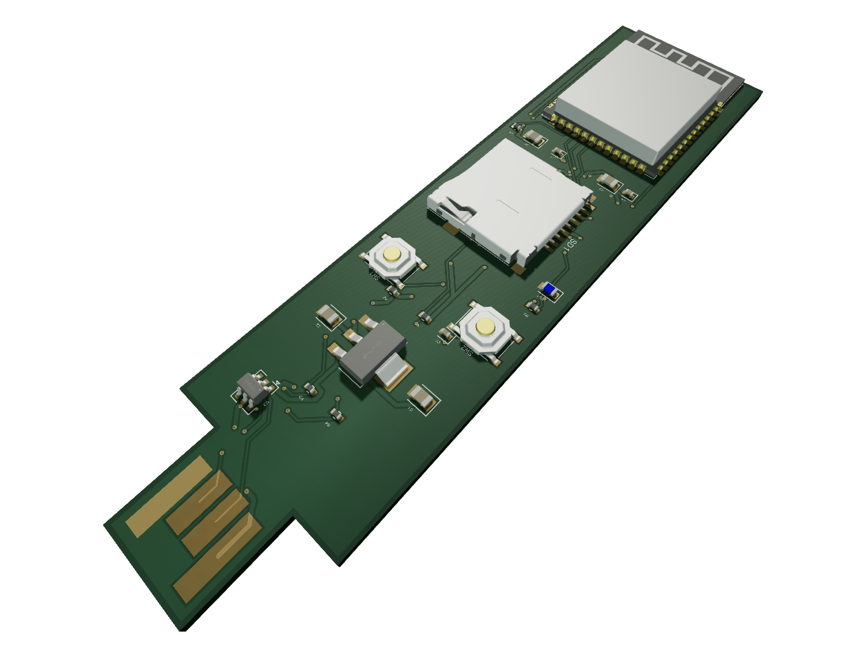
i found a youtube vid on kicad and the guy did gold fingers for the usb -a so i asked tsciruit to do the same by giving it a screenshot, pretty impressed, not sure what i need to tell jlcpcb to do to get those gold fingers
mohan-bee
that looks good . maybe you can cancel the order from jlcpcb , and re order
pixalynx
they wont let me cancel i just went ahead with the component swap
mohan-bee
oh
pixalynx
I might mill this pcb on my cnc, but i've never soldered in my life so this will be fun haha
Seve
looks awesome, yea would love to see a male usb with gold fingers
Seve
somebody has figured out how to do it with usb-c also haha
Seve
have not tried that myself yet
pixalynx
WHAAAT
pixalynx
I NEED !
Seve
yea it's kind of wild
pixalynx
fable couldnt do it !!!! it told me it was impossible
pixalynx
Short answer: USB-C with gold fingers only — no, that one's genuinely impossible, not just hard. But the USB-A style in your screenshot is very doable, and it's actually better than what your board does now. Let me explain both.
Seve
trying to find the guys on x
Seve
https://x.com/CapacitAnas/status/1982060711670067350
Seve
there is apparently an implementation here: https://github.com/vasya-zh/PCB-Edge-USB-connector-KiCad-library
pixalynx
haha this was claude's response - I owe you a correction: I was wrong. I told you USB-C edge fingers were "geometrically impossible" — this repo proves they're not. I over-reasoned the mechanics. Here's what they actually did, confirmed from the footprint file itself.
Seve
yea it's ok AI is often wrong in electronics right now
Seve
it'll get better
pixalynx
the fact that i even made a pcb with 0 electronics experience blows my mind haha
Seve
yea it's super cool
pixalynx
hey another question, if im not using a usb how does one flash firmware to a microcontroller, for my most recent pcb when it arrives ill plugin via usb and press the buttons to get the flashing going, but if we dont have a usb connector what is the way ?
Seve
there are tons of options
Seve
i would add a male or remale pinheader, then attach the SWD programming pins to a breadboard, then plug that breadboard into an RP2040 XIAO (any XIAO will work)
Seve
what we do internally at tscircuit for all our boards is use a JST connector to a XIAO
Seve
there are lots of ways but basically you need to be able to plug into the SWD pins, SWD = SoftWare Debug
Seve
even with USB, sometimes you can't program

Want to add to the conversation?

Reply in Discord so your notes stay connected to the source.
Continue in Discord ↗