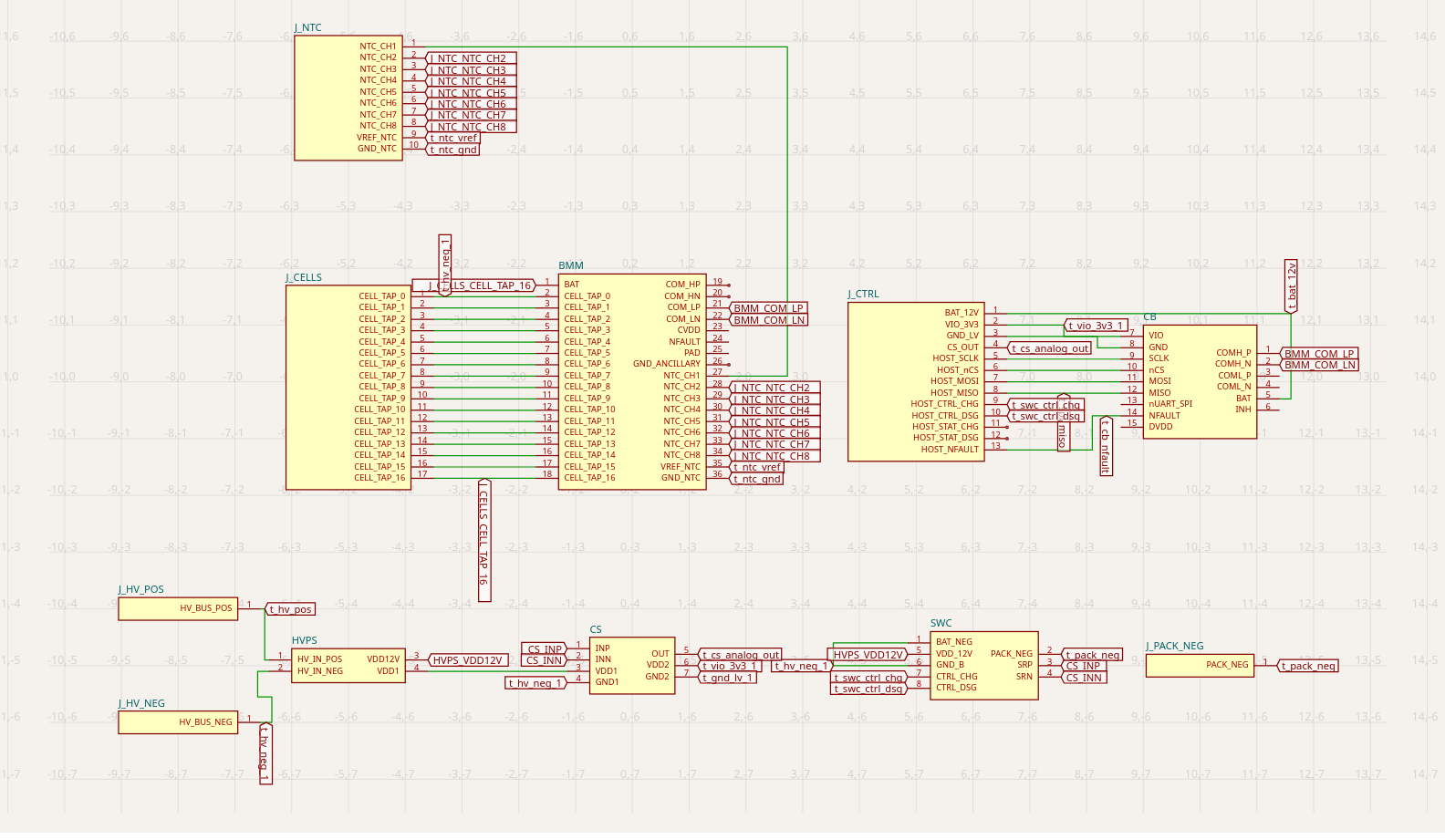
Hi guys.. code sample These are all the features directly available for tsci screenshot Is it possible to get the grid coordinate information (for both schematic and layout) in the screenshot? Something like the attached image? As of now grid option is available only in schematic
Hi guys..
```
± |master {4} U:1 ?:1 ✗| → tsci snapshot --help
Usage: tsci snapshot [options] [path]
Generate schematic and PCB snapshots (add --3d for 3d preview)
Arguments:
path Path to file, directory, or glob pattern (e.g., 'examples/**/*.tsx')
Options:
-u, --update Update snapshots on disk
--force-update Force update snapshots even if they match
--3d Generate 3d preview snapshots
--pcb-only Generate only PCB snapshots
--schematic-only Generate only schematic snapshots
--simulation-only Generate only simulation snapshots
--layer <layer> Generate a PCB snapshot for one layer: top or bottom (implies --pcb-only)
--disable-parts-engine Disable the parts engine
--show-courtyards Show courtyard outlines in PCB snapshots
--camera-preset <preset> Camera angle preset for 3D snapshots (implies --3d). Valid presets: top-down, top-down-ortho, top-left-corner, top-left, top-right-corner, top-right, left-sideview, right-sideview, front,
top-center-angled
--ci Enable CI mode with snapshot diff artifacts
--test Enable test mode with snapshot diff artifacts
--concurrency <number> Number of files to snapshot in parallel (default: 1) (default: "1")
-h, --help display help for command
```
These are all the features directly available for `tsci screenshot`
Is it possible to get the grid coordinate information (for both schematic and layout) in the screenshot? Something like the attached image? As of now grid option is available only in schematic, is something similar available in pcb layout?
In fact, it is better if we can get a textual representation of the PCB(Layout) and Schematic component placement with their exact borders, co-ordinates etc.
V
Vivek Vijayan
I'm trying to implement a layout design agent based on LLM. Initial component placement can be achieved through ML approaches like Cypress(https://github.com/NVlabs/Cypress). But targeted component placement can be better achieved through LLM AI Agents.
V
Vivek Vijayan
My mistake.. I think, Answer to my question is already present at the roots of tscircuit, circuit.json... Instead of feeding the schematic/pcb images, I will try to feed circuit.json to the agent and do the analysis.
V
Vivek Vijayan
I've prepared a skill for circuit-json analysis according to Anthropic Agent Skill standard. Would love to see your feedback on this.. Any suggestions on missing important features or concepts are welcome..