astrimid - Another day, another bug. Using <net...
Another day, another bug. Using <netlabel with <schematicbox. I see the example https://docs.tscircuit.com/guides/tscircuit essentials/splitting a component across schematic sheets uses <resistor connections prop which use U1 references instead of U1A or U1B. This is fine, I gues
Another day, another bug. Using `<netlabel` with `<schematicbox`. I see the example https://docs.tscircuit.com/guides/tscircuit-essentials/splitting-a-component-across-schematic-sheets
uses `<resistor connections` prop which use `U1` references instead of `U1A` or `U1B`. This is fine, I guess.
But it's unclear what behaviour should be if we try to attach the `<netlabel>` pulling some pins to the `GND` net for example.
`<trace` is easier to understand for electrical connection and PCB trace.
But as `<netlabel` is purely documentational (even though its `connection` and `net` properties implicitly creates a trace), placing it on schematic position using `schX` and `schY` has some strange behaviour wrt to attaching to pins or schematic boxes.
So, using both `<netlabel` and `<schematicbox` with reference to `<chip` I think is undefined behaviour. Because if you reference chip name in netlabel connections, you would expect autocreated trace to be connected to chip pin. But as chip pin is being represented by a schematic box, you'd probably also expect the trace from schematicbox as well. But trace represents both electrical connection and pcb trace, and there's no schematic only wire that doesn't create a self referential connection.
So as schematic box is introduced, I guess a schematic trace/wire is needed as well?
First of all, let's ignore this bug/missing feature. As I place a `<netlabel/>` using `schX/schY` , the automatically placed netlabel doesn't disappear, even though it's redundant. I can create a separe thread about if required.
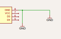
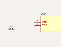
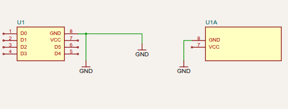
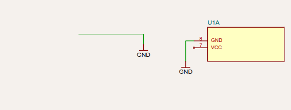
As we can see, the trace is created from GND to U1. But there's no trace from GND to U1A. I'm not sure if duplicate trace should be created, but it looks there's no way to control which schematic box the wire created using `<trace` or `<net` should connect to?
A
astrimid
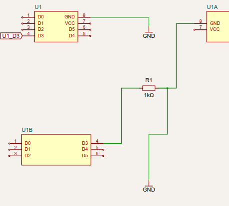
On the other hand, as I introduce a resistor between another pin of the chip and the GND, the trace to GND magically added to U1A. For the D3 pin, we see a wire from U1B to R1, and a net label for U1 corresponding pin. This makes me suspect that the missing GND trace for U1A is some implicit intended behaviour, as we don't see a port symbol (a circle at the end of the pin).
So why would a wire be drawn to the schematic box in one case, and to the chip in another? This seems random.
As I try to do explicit `".U1B .D3"` selector, the compiler says `"Could not find port for selector ".U1B .D3". Component "U1B" found, but does not have pin "D3". It has no ports"`
Hey <@1525187702029549659> , when using manual net labels, you need to connect each one individually. Anotherside You can simply connect `U1` or `U1A` directly to `net.GND`, and they will all be connected through the same `GND` net label automatically.
A
astrimid
<@1067854999889137715>
have you checked the example I provided? What do you mean by "connect each one"?
A
astrimid
And how do I connect `U1A` if it has no ports, according to compiler?
T
techmannih
<@1525187702029549659> I think I found the issue. You're using the same pin labels for both chips U1 and UA1 . For `U1`, you've already used `pin7` and `pin8`. Since `pin8` (`GND`) is already connected on `U1`, `pin8` on `UA1` is automatically disabled for porting. That's why the compiler reports that it has no port.
I am not sure it is bug cc <@757706909351411845>
A
astrimid
But they're the same pins. They should match, otherwise the schematic wouldn't make any sense
T
techmannih
Yeah, I think they should match and connect instead of disabling the other chip's pins. I'm not sure though, <@757706909351411845> can probably help in this case.
A
astrimid
Also, the example seem to be having no problem reusing same pin numbers: https://docs.tscircuit.com/guides/tscircuit-essentials/splitting-a-component-across-schematic-sheets
although it doesn't make sense. I think it kind of works there because they're on different schematic sheets, so each schematic box is namespace isolation.
A
astrimid
I belive it should actually disable the other chip pins, but it should be controllable via API, not implicitly chosing randomly either schematicbox or the chip. Alternatively, it should throw an error saying there's a namespace conflict and you can't have both schematicbox and chip in the same subcircuit namespace.
A
astrimid
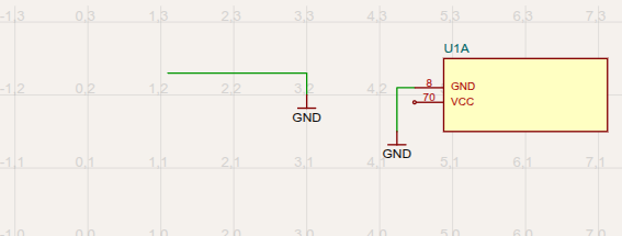
I've tried using `noSchematicRepresentation` on `<chip` but the behaviour is even more bizarre:
So the only way to use `<schematicbox` is via isolated sheets or subcircuits, like on example? This makes the `<schematicbox` nearly useless
A
astrimid
the `<schematicbox` should be a schematic view of the same `<chip` source, not independent component you must isolate into a separate namespace.
A
astrimid
Ok, the workaround of putting the `<chip` into `<subcircuit` works:
https://tscircuit.com/editor?&snippet_type=board#data:application/gzip;base64,H4sIAEMUYmoAA8VVbU/bMBD+K6doHwCN9BWGOsJUaAdIU0EtZZuWCdLEJRapXTmuWinqf9/ZieO0FDHxhX5qnzvfy3PPXTOHsoisXJmunI4TcpZKCGM6HwQzAh74zrjhOz6zhhFJSCi5QOOju+TiORB8wSJwP2Xm3frxq3kx50siRjEhshIQbhVqw1L+wuO6drOdNpSUs580kjE6Nd1m+2iH/YrQp1iiQ8NnNvwtZT+CCUlSNGQ+A5hT1uhgpl7ddz4XQFMD2K0BWhpoWqCtgZYFjjTQtsCxBo40sLYVaBZ2FfFF+d9fXNgIJwq5HPS2QwRJ8iFd/HeZZDXnQkJEpsEikbC3D94Z7Cn30wkPRHSmvuKPdDEJqQgXVALDgXu+Y0XkO4UX+qmhmh8AU87lXFAm0T/lNDxR6jDGNIx/eVkdy6ggv72sWUGKXLmaDYiN5Ix6WZXf8lnNFF2zVSNkOgljMgskDSd8ZV7kpRyXEbYLKcvo2jpUp0My9fT+mPUqXyyV4o3N7kBpj7XiNxzyJSg9Kl1uCrFaJYJdIQL2RGYEWc60wPJPQqZyRCPSgT9m5kYOf7Ue8o9QSQs/i6+LJIrKN3mzI8x5O2y8JO78Q4ir3JD3sKY31CxmsY+vcVcsp9nJYhV3M6r5ZKRcJT2dCtdZ7QDGg17/+/Wg34Pz/lX3/vpmPOzAKOaLJAIZE8DniWoM8NAw5AEkB7zAeOFRpd/goFbkU3lyx3xYrXWpbhWjzF6ESe+4npdra1JRbF3dwc3dVX8Io7thd3DZh/PxpU2GDkVWQVKa4lw3ldJ6UynDyqbnMQIWKkPj2RqqZ6XeruNUSm3lXaAocPpZeWo3/vGQJTeflTm8yEPR764p7WTvEL+9St+w4arQFf5OpQhCHFreZNR6QPuD5A9P6nrCVPAZwrYMuTtKwfNpzZzmfZ8563/e1jDTDAgAAA==
Yeah, I'm out of ideas. There's no way to hide the `<chip` from schematic
R
Rishabh
I will check this out, this feature was merged yesterday. It might have bugs
Seve
yea it is a very new feature- we'll get this figured out- we are doing some pretty large schematics with it so we are incentivized to get all the bugs fixed asap
Want to add to the conversation?
Reply in Discord so your notes stay connected to the source.